
For car enthusiasts and DIY mechanics, delving into vehicle coding and diagnostics often becomes a necessity, especially as cars age and require more intricate maintenance. Tools like INPA are invaluable, but issues like FRM failures due to insufficient power can be frustrating. Commercial car coding power supplies, while reliable, can be expensive, often ranging from $300 to $700 for models like the MST-80 or Schumacher INC-700A. The good news is, there’s a cost-effective alternative: repurposing server-grade power supplies.
These power supplies offer several advantages for car coding applications:
- Cost-Effective: Server power supplies are significantly cheaper than dedicated car coding units.
- High Amperage: They provide ample power, crucial for stable voltage during coding processes.
- Efficient: Designed for server environments, they are built for efficiency and reliability.
This guide will walk you through converting a server power supply into a robust Car Coding Power Supply, perfect for maintaining a stable voltage during those critical coding and programming sessions.
Why a Server Power Supply for Car Coding?
Using a server power supply for car coding isn’t just about saving money; it’s about accessing reliable power for sensitive electronic work on your vehicle. Car coding and ECU programming demand a stable voltage supply to prevent data corruption and module damage. Fluctuations in voltage during these processes can lead to serious issues. A dedicated car coding power supply ensures a consistent 14V output, crucial for maintaining your car’s electrical system during coding.
Server power supplies are designed to deliver clean and stable power in demanding environments, making them ideal for this repurposed role. Their high amperage output easily handles the power demands of car electronics during coding, far exceeding the needs of basic battery chargers.
Parts List for Your DIY Car Coding Power Supply
To build your own car coding power supply, you’ll need the following components. Sourcing these parts can be done online or from local electronics suppliers.
- Server Power Supply (HP DPS-1200FB A HSTNS-PD11): The heart of the project. Look for models like the DPS-1200FB which are readily available and powerful.
- LCD Digital Display Multimeter (6.5-100V, 0-100A): For monitoring voltage and amperage output.
- Round Rocker Switch: To control the power supply’s on/off state.
- 8AWG Booster Cables: For heavy-duty power delivery to your car.
- 8AWG Wire Lug Ring Clamps: For secure connections to the power supply and battery terminals.
- Resistors (22kΩ, 75kΩ, 15kΩ): For modifying the power supply’s voltage regulation. (82kΩ and 18kΩ can be used as close substitutes if 75kΩ and 15kΩ are unavailable).
- Old Electric Stapler Case (or similar enclosure): To house the power supply components safely.
- Solid Core Wire (Various Colors): For internal wiring.
Estimated Total Cost: Approximately $91 USD (Cost may vary based on component sourcing and availability).
Step-by-Step Conversion Guide
1. Resistor Modification for Voltage Adjustment
The first crucial step is modifying the server power supply to allow for voltage adjustment up to 14V, which is essential for car coding. By default, these power supplies are set to a lower voltage.
- Locate Pins 33 and 32: On the power supply connector, identify pins 33 and 32.
- Solder a 22kΩ Resistor: Solder a 22kΩ resistor between pin 33 and pin 32. This is a key modification to enable the power supply to turn on and function correctly for our application.
2. Adjusting Voltage Regulation Circuitry
To achieve the desired 14V output and overcome the Over Voltage Protection (OVP), further resistor modifications are needed on the edge circuit board inside the power supply.
- Open the Power Supply: Carefully open the power supply to access the internal circuit boards. The edge circuit board is where the voltage regulation components are located.
- Locate and Replace Resistors: Identify the resistors in the regulation circuitry. You’ll need to replace existing resistors with a 75kΩ resistor and a 15kΩ resistor. In this example, 82kΩ and 18kΩ resistors were used as close substitutes and are acceptable.
- Soldering the New Resistors: Carefully solder the new resistors in place. Ensure proper soldering technique to avoid cold joints. Insulate the resistors with electrical tape or Kapton tape to prevent short circuits against the circuit board.
3. Voltage Output Adjustment
- Locate the Potentiometer (Pot): Find the potentiometer on the circuit board. This is used to adjust the voltage output.
- Adjust to 14.2V: Use the potentiometer to adjust the output voltage to your desired level, ideally around 14.2V. Remember that the voltage may slightly decrease under load (when amperage increases).
4. Wiring and Connections
- Power Cables: Cut a length of the 8AWG booster cable (approximately 1 meter) for connecting the power supply to your car battery clamps. Using thicker gauge cable is beneficial but can be harder to work with.
- Rocker Switch Installation: Wire the SPST rocker switch to complete the circuit between pin 36 and ground. This switch will act as your on/off control for the 14V output.
- Internal Wiring and Assembly: Use solid core wire to connect the components internally. Employ zip ties to secure the circuitry within the enclosure, ensuring wires are neatly organized and won’t be pinched when closing the case.
5. Enclosure and Ventilation
- Enclosure: Place the modified power supply and components inside the chosen enclosure (like the electric stapler case).
- Fan Ventilation: Cut a hole in the side of the enclosure to allow the power supply fan to vent hot air, ensuring proper cooling during operation.
Usage and Safety Notes for Your Car Coding Power Supply
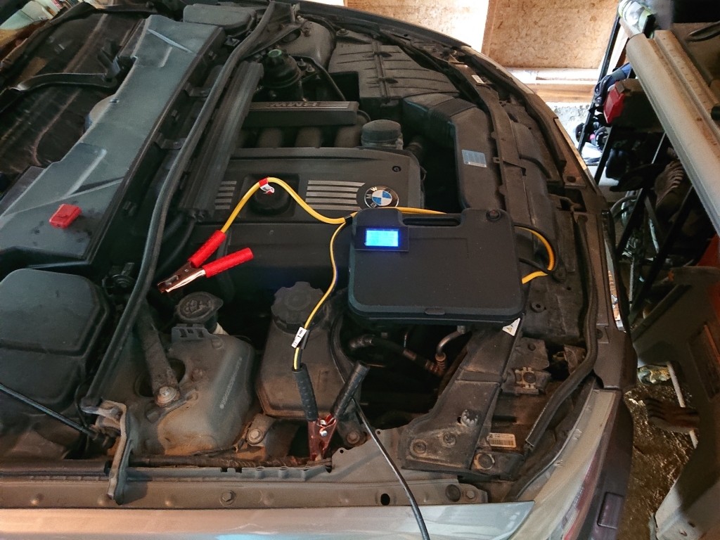
- Power On Sequence: Always turn on the car coding power supply BEFORE connecting it to your car. This prevents potential issues related to reverse current.
- No Reverse Polarity Protection: This DIY setup does not include reverse polarity or short circuit protection. Exercise caution when connecting to your car.
- Fan Operation: The power supply fan will continue to run as long as the unit is plugged into mains power, even when the 14V output is switched off. This is normal.
- Discharge Time: Allow approximately 20 seconds for the power supply to fully discharge after being switched off. Do not touch the clamps together or place them down immediately after turning off the power supply until the voltmeter reading confirms discharge.
Conclusion: Empower Your Car Coding Projects
Building your own car coding power supply from a server power supply is a rewarding and economical project. It provides a reliable and powerful 14V source essential for successful car coding and ECU programming, all at a fraction of the cost of commercial units. By following these steps and safety guidelines, you can confidently power your car projects and coding endeavors.